|
Help | | | News | | | Credits | | | Search | | | Guestbook | | | Forum | | | Shop | | | Contact Us | | | Welcome |
Westwood Works 1903-2003 |
|||||||||||||||||
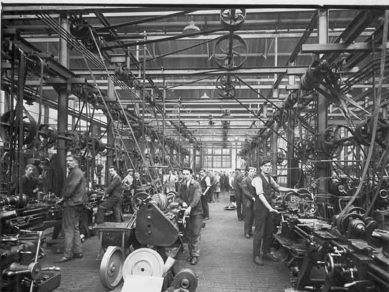
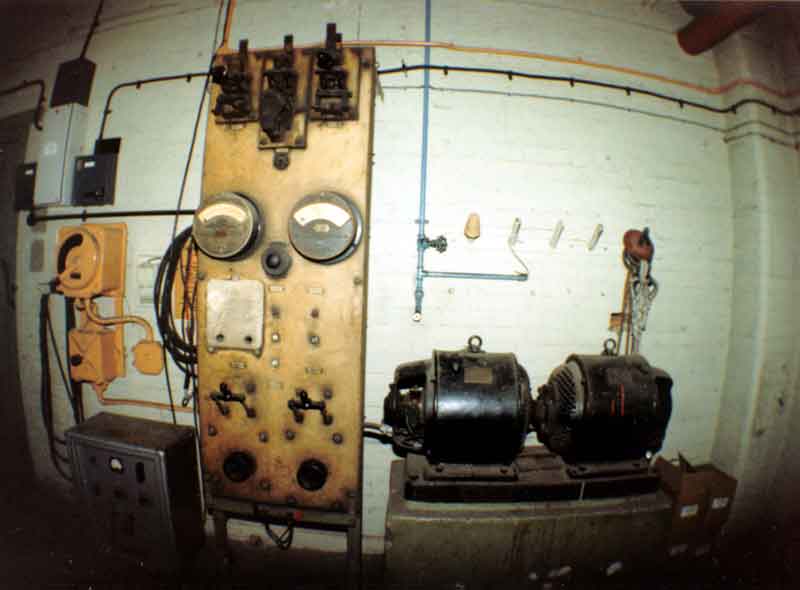
Behind the scenes in every factory exist the means to provide the "services" - power, both permanent and stand-by, steam, hot water, compressed air, etc. The equipment needed to meet these needs has evolved significantly over the last nearly 100 years. The most obvious outward manifestation is perhaps the change from the lineshafts and belt-drives for powering the machine tools shown in the 1923 photographs, to the electronically controlled equipment used in the Factory in the later years. We are still developing this section and would like to hear from anyone with information about the development of the Power House, Boiler House, Stationary Diesel Engines, etc., over the past 100 years. For example, can anyone identify the equipment shown in the photograph of "The Power House" in 1923 please?
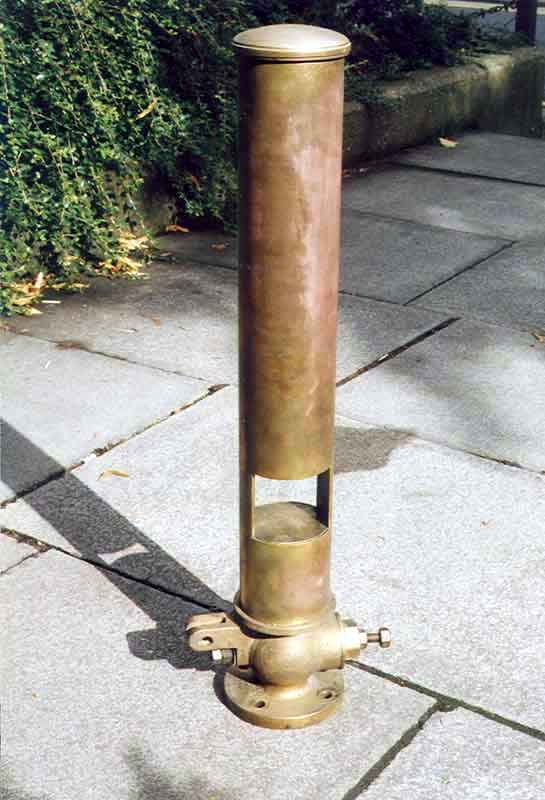
It could be heard a long way from Westwood; depending on the wind direction, Fletton, Walton and Dogsthorpe were certainly within its range. Many Peterborough residents who were not Westwood employees depended on it for their timekeeping.
It sounded eight times a day, Monday to Friday, at the following times:
07.15 - First Warning.
07.25 - Last Warning (At this time it was sounded twice).
07.30 - Final - All employees should have clocked on by that time. (see "Clocking
On" in Getting
to Work).
12.30 - Mid-day Lunch Break.
13.15 - First Warning.
13.25 - Last Warning (Again being sounded twice).
13.30 - Final.
17.30 - Leaving Work (For a 42 ½ hour week; 4.30pm when working hours changed to a 40 hour week).
 |
At the end of the morning and again at the end of the day, "knocking-off" time
was also signalled by a single sounding of an internal buzzer. This was also
sounded at 7.30pm on Tuesdays and Thursdays to mark the end of official overtime.
Bert Slater recalls : "As I lived in Paston Lane I liked to have been cycling down Walpole Street by the time that the 7.15am hooter sounded, so that parking my cycle and clocking-on had been done by about 7.20am. As you can imagine, many people left it to the last minute and, with about 2,000 employees it was a bit of a scramble." |
| The Factory Hooter |
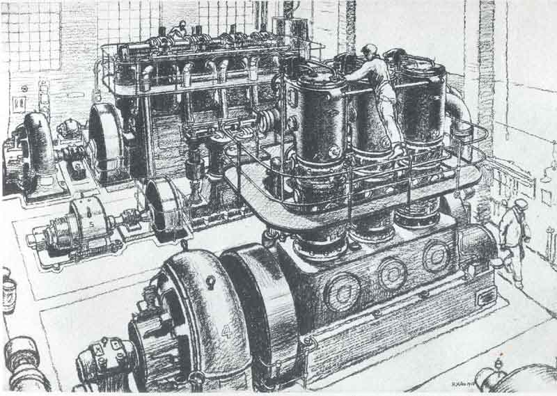
When the factory in Westfield Road was first built, power was derived from a central station provided by a 275 horsepower gas engine, driven by producer gas and directly coupled to dynamos. The whole distribution of power and lighting was by electricity at 220 volts. Messrs. J.H. Andrew & Co., Stockport supplied the gas engines and the International Electrical Engineering Co., the electrical equipment.
 |
 |
 |
| "The Power House" by Rudolf Ihlee | 1923: The Power House | 1923: The Small Lathe Bay |
The 1923 photo of the Small Lathe Bay clearly illustrates the lineshaft and belt drive system used throughout the factory to power the machine tools. It is debatable whether such a system would pass today's Health and Safety regulations.
Jim Deboo tells us that during the Second World War, much of the machine shop was still operated by line shafting, with each line driven by one 50hp electric motor through a 9" wide x 5/8" thick leather belt. The beltman came in on dayshift at about 6.30am (an hour before he was required to and entirely voluntarily) in order to check, and correct if necessary, the running of the lineshafts at the end of the nightshift and before the dayshift began work. Harry Lunn and Frank Goslow were among those responsible for this over time. On occasions in winter, Frank came to work in his horse and trap which he then stabled in the cycle sheds.
It was vital to have a competent beltman on hand to deal with breakages. When a main drive belt broke, it sounded like a gun firing and then silence followed, as a whole row of machine tools came to a halt. This was both expensive in lost machining time and also dangerous because loss of power to a machine tool under load whilst cutting (e.g. turning a huge mixer blade, cutting a square thread on a lathe, milling a flat surface or cutting a gear) meant that the cutting tool could break or remain jammed in the work piece.
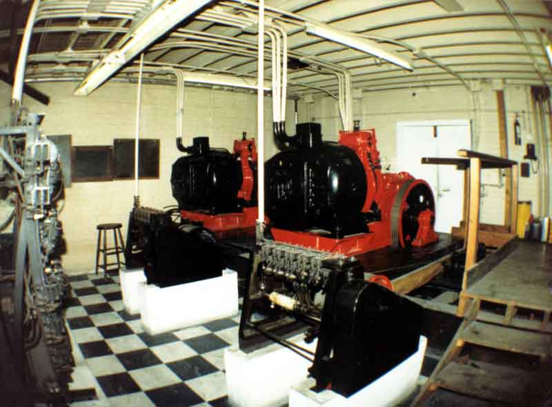
Jim also remembers that in the war years there were two large stationary diesel engines in the power house. The largest was a 500hp Swiss Sulzer with a 9' diameter flywheel which drove a DC generator. On one occasion during a weekend, Jim had to machine a 24" diameter block of high grade cast iron to make a new cylinder head to replace one that had "blown".
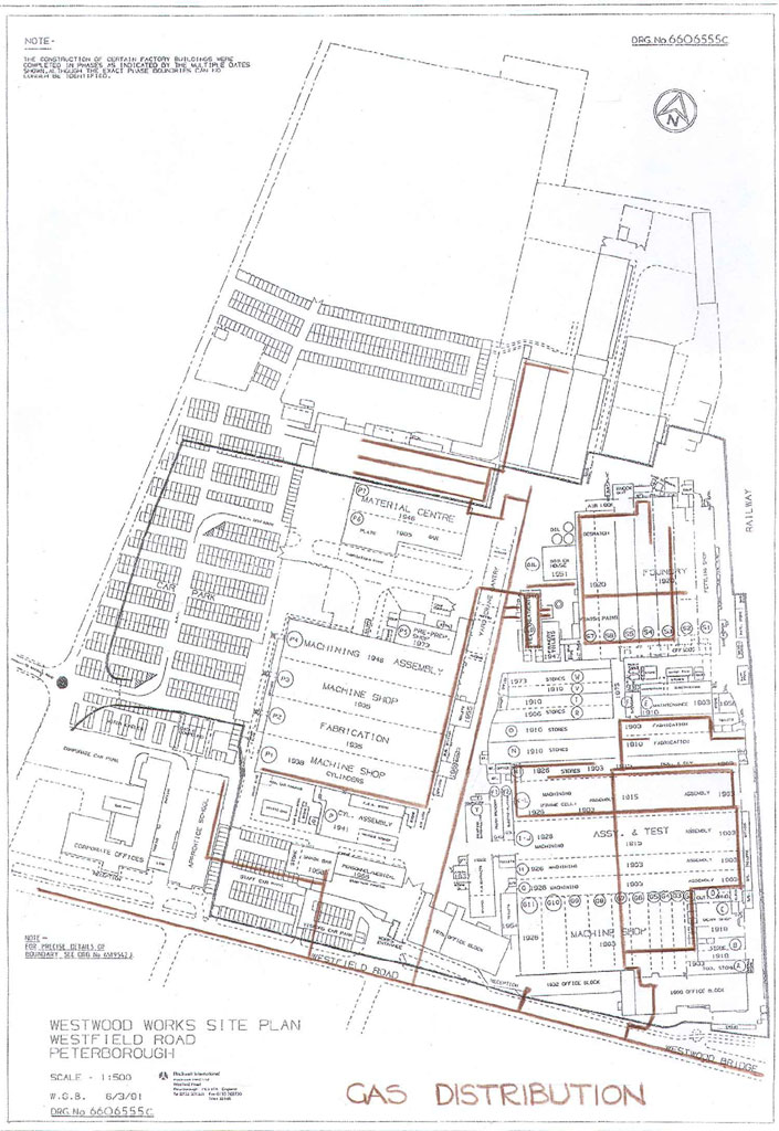
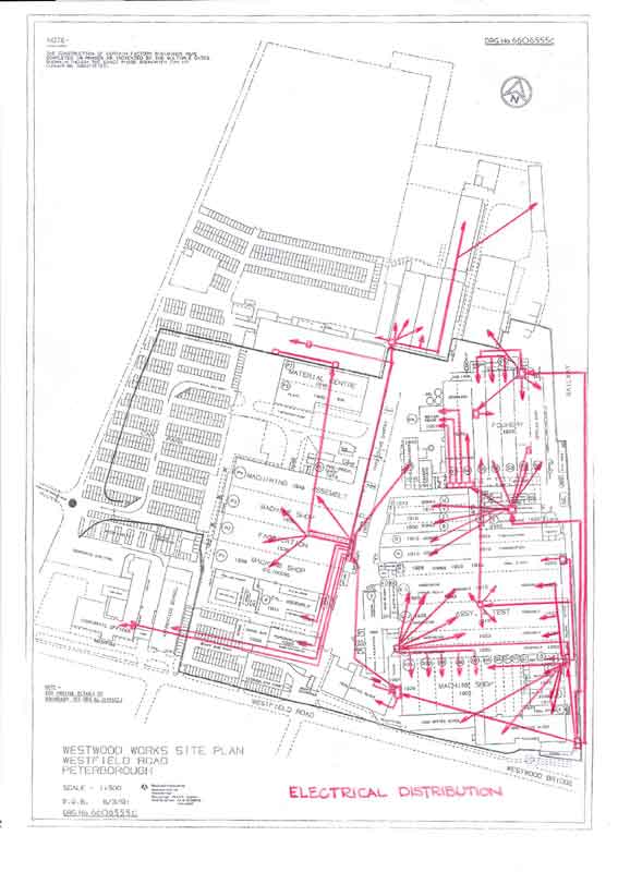
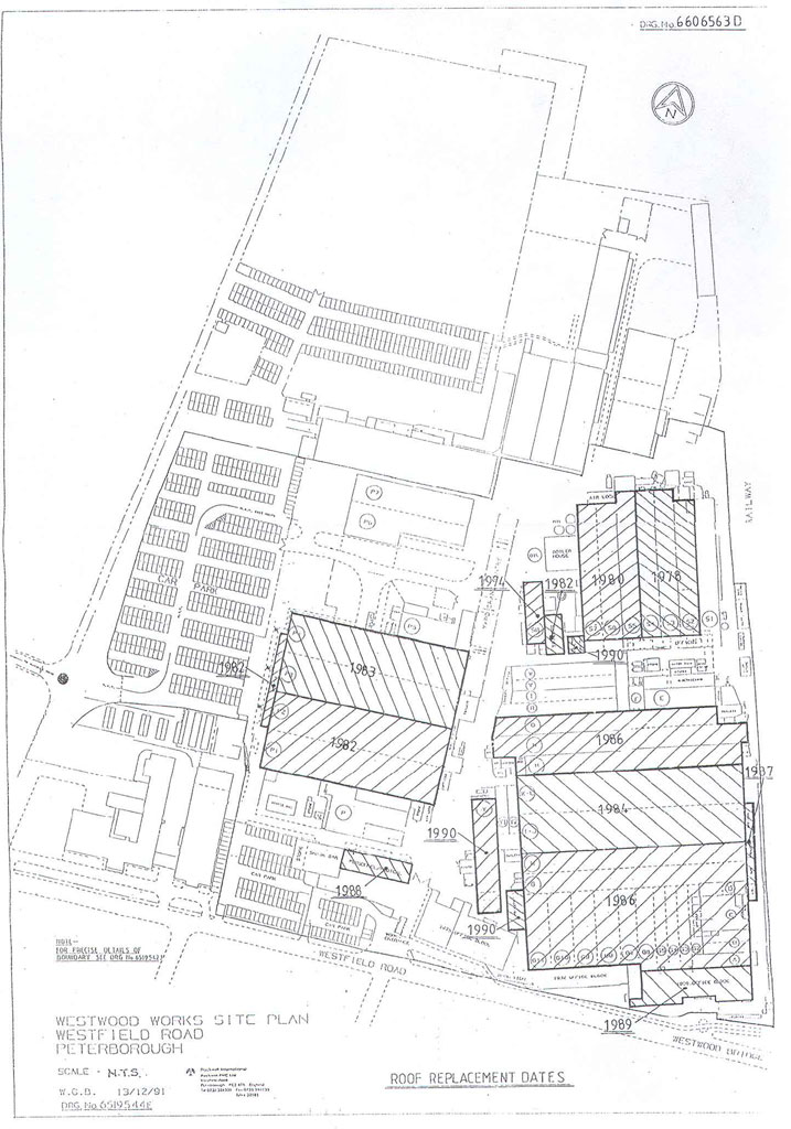
As the 1940s progressed, more machine tools were fitted with, or were supplied with, integral electric motor drives. The increased sophistication of equipment used, culminating in the numerically controlled machine tools of the 1970s/1980s, demanded ever increasing supplies of power. The 1960s 6,600V supply was increased to 11,000V in later years. The complex distribution system for this is shown on the site plan below. In addition, the cranes and lifts on the site were powered from a DC supply in the Maintenance Department.
 |
 |
 |
 |
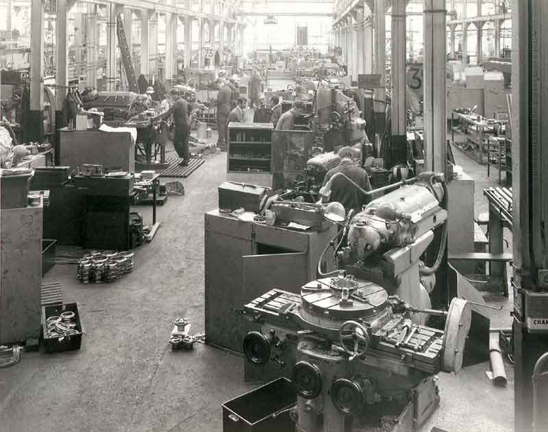
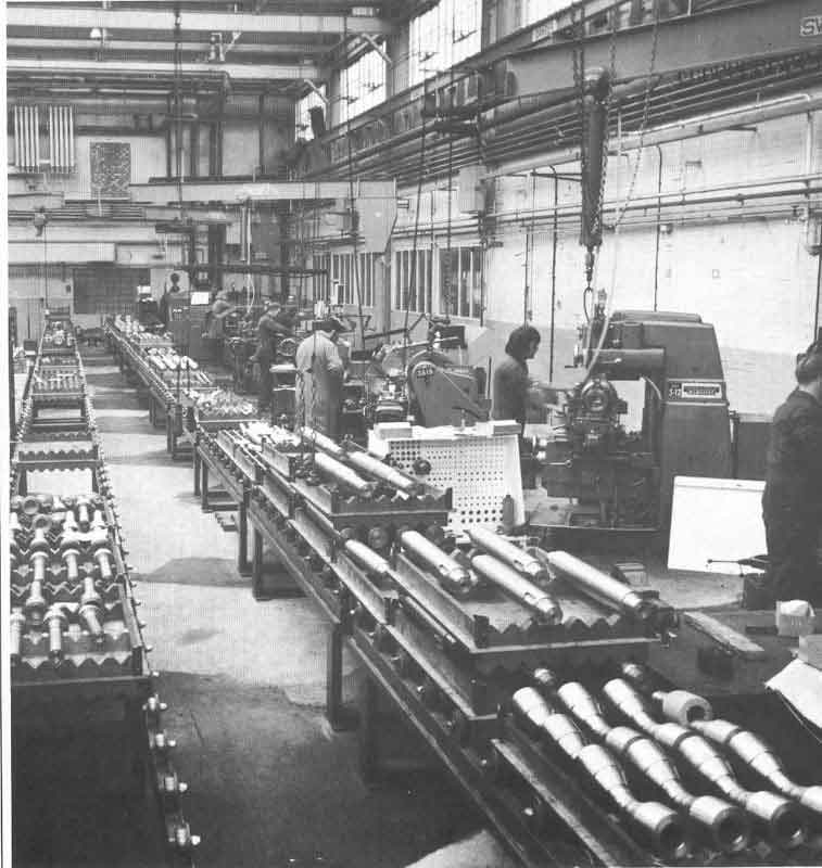
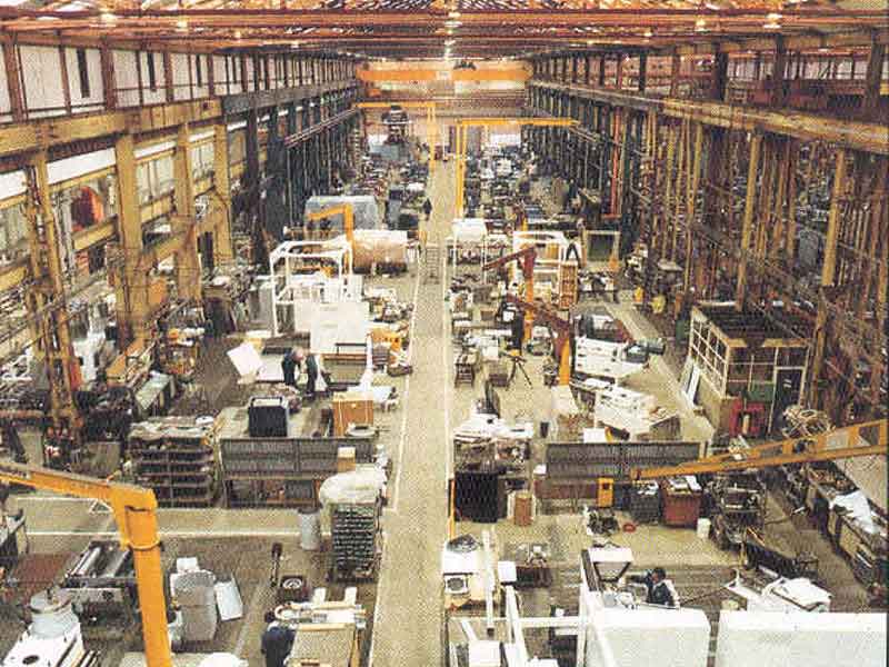
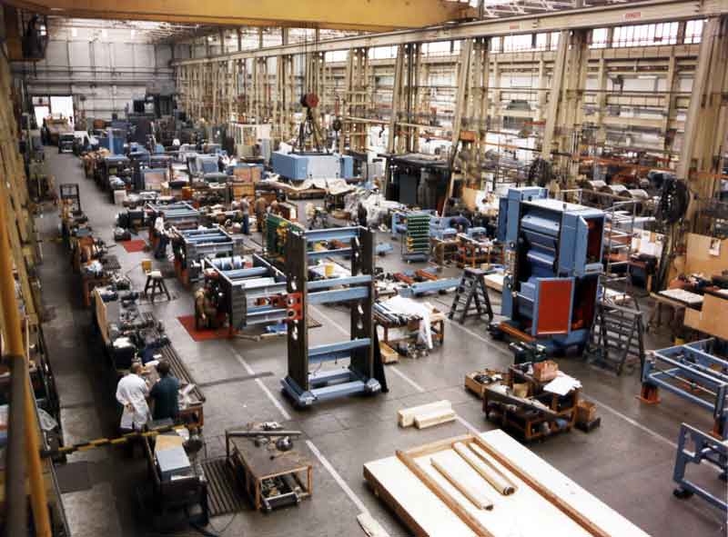
| Site Plan: Electrical Distribution | 1970: The Small Milling Bay | 1982: Group Technology Component Manufacture | 1982: Automatic machining of Biscuit Rolls |
Compare the photograph of the 1923 Small Lathe Bay with that of the Small Milling Bay in 1970 and both of these pictures with the dramatic changes illustrated in the 1982 photographs shown above.
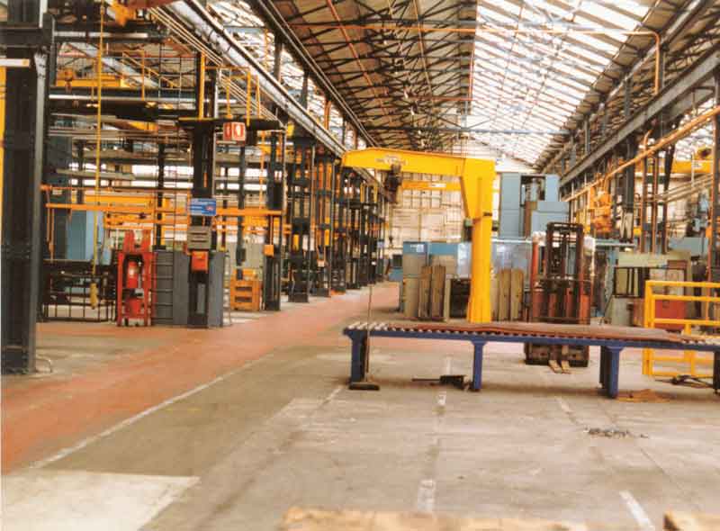
It will be seen from the 1907 Sales brochure in Documentation that WP&P were experts in central heating systems, supplying a system to St. George's Chapel, Windsor among many others. Loftus Perkins had patented a stopped-end steam tube system, consisting of wrought-iron tubes, partially filled with distilled water, with both ends hermetically sealed. One end of the tube was positioned in a furnace creating in effect, an individual boiler, its upper part filled with high pressure steam. This formed the basis of an entirely new and efficient baking system in which the tubes traversed the whole length of the oven both above and below the product being baked, providing a steady level of heating. A similar idea was used for space heating. The photographs of the main workshops, from those of Westwood Works in 1923 to those of the empty factory prior to demolition<, clearly show banks of heating tubes hanging from the stanchions on both sides of the workshops. In the early days, these were heated by coke stoves at the end of each shop. These were still in place during WW2 and in the Machine Shop and Fitting Shop, these coke-fired furnaces were about the size of a drawplate oven and provided hot water and steam heating to various parts of the workshop.Jim Deboo writes: "In winter, during our 30 minute meal break from 2.30am to 3.00am, we would gather round the open furnace to eat our food."In later years, after the Boiler House with its prominent chimney, was built in 1951, the same pipes were used to carry steam from the central boiler. Even later, this system was improved by the addition of fan heaters positioned at intervals along the pipe system.
 |
The Space Heating Steam Distribution system in place prior to the closure of the factory |
Prior to the building of the "new" Boiler house in 1951, there were three coal-fired boilers, two in use - one on "stand by", housed in a building in the main Works yard, just north of the Fire Station. Coal was stored in hoppers high above the ground and fed to the furnaces by chain-grate and screw feeds.
 |
 |
 |
 |
 |
||
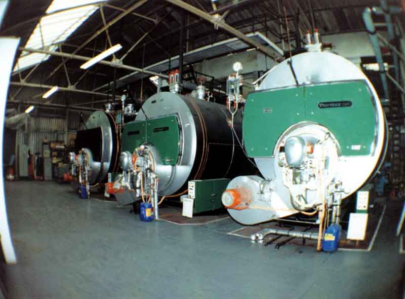
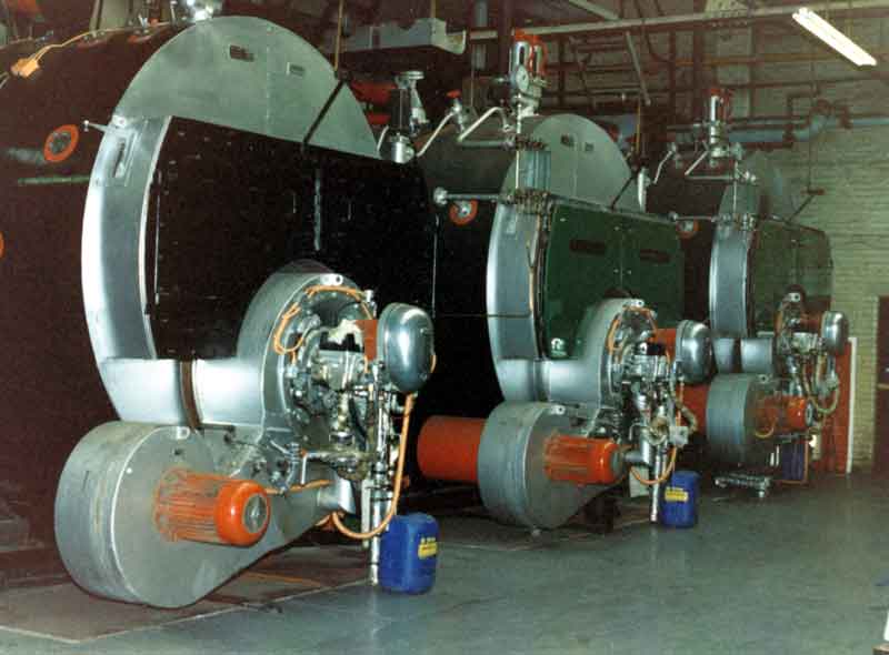
| Rear of the inside of the Boiler house | Cleaning out the Boiler House | Ruston Thermax boilers | ||||
Each of these boilers was capable of producing 14,000 lbs of steam per hour. Emergencies were catered for by standby boilers in the Fitting Shop and Experimental Department.
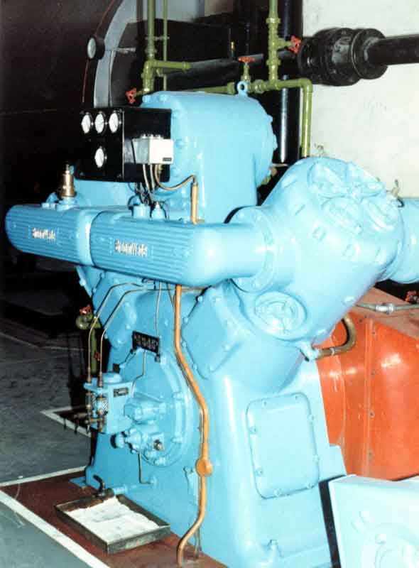
Supplies of compressed air were needed at many points in Westwood Works and by the 1970s, a number of individual compressors scattered around the site had been replaced by larger Broomwade compressors. These supplied 11,000 cfm and were located centrally in the Boiler House.
 |
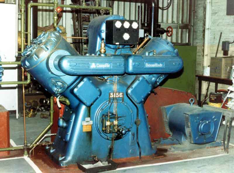 |
| Broomwade compressor | |
|
Gas supplies to the site were tapped off at four points along the main supply in Westfield Road |
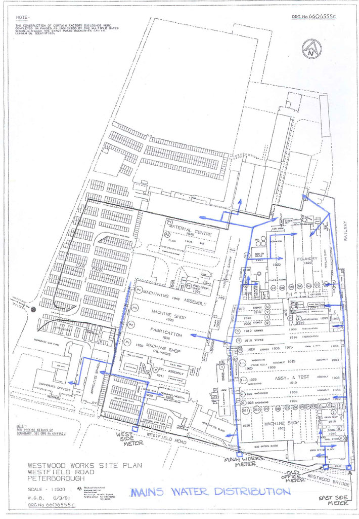 |
Mains water was fed via 4 meters from the main in Westfield Road. A factory like Westwood Works used a significant amount of water - the four meters were capable of a total flow rate of 535 cubic metres per hour. |
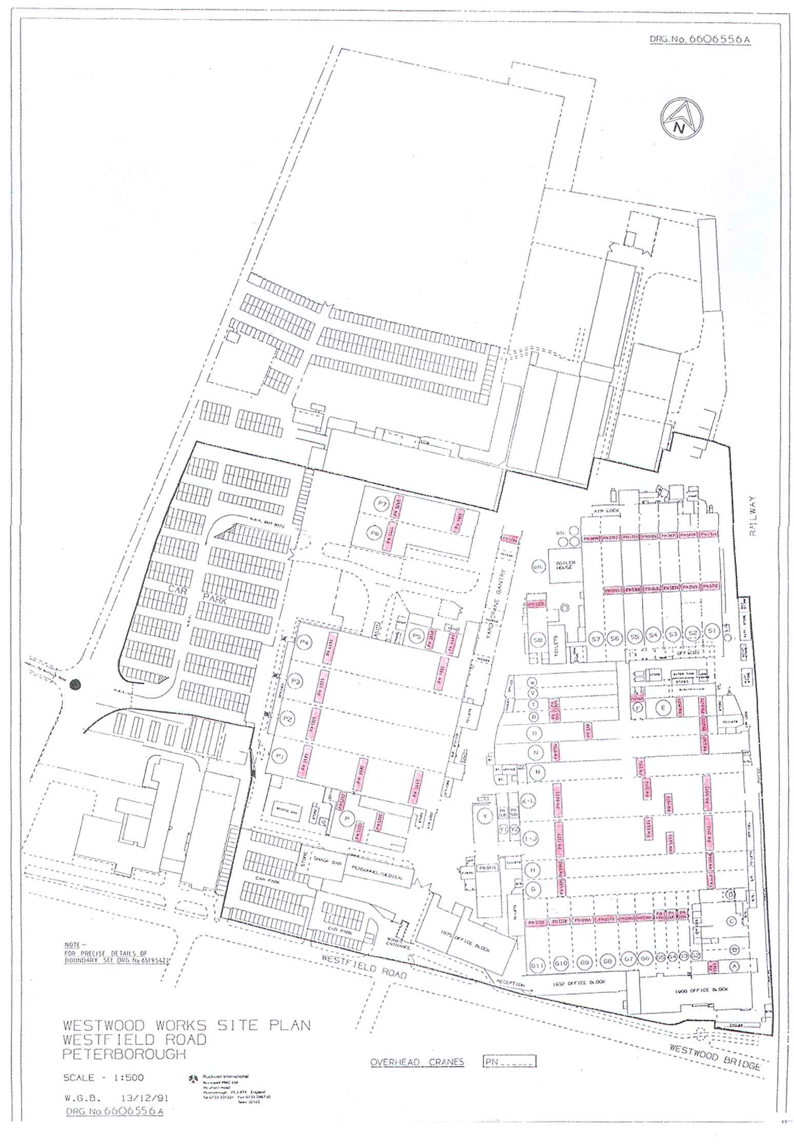
A most essential part of any engineering factory are the workshop cranes. Including the yard gantry crane, there were over 60 cranes at Westwood Works. These ranged from the 20 and 30 tonne capacity double girder cranes in "KL" and "IJ" Bays to the 0.5 tonne and 1.0 tonne single girder units used in the smaller bays. All of the bigger bays had two overhead cranes. This does not include the small hoists used fro loading individual machine tools and for erecting machines in the Fitting Shop. Approximately twelve of these cranes date back to the first WP&P factory having been installed between 1906 and 1926.
 |
 |
 |
 |
 |
 |
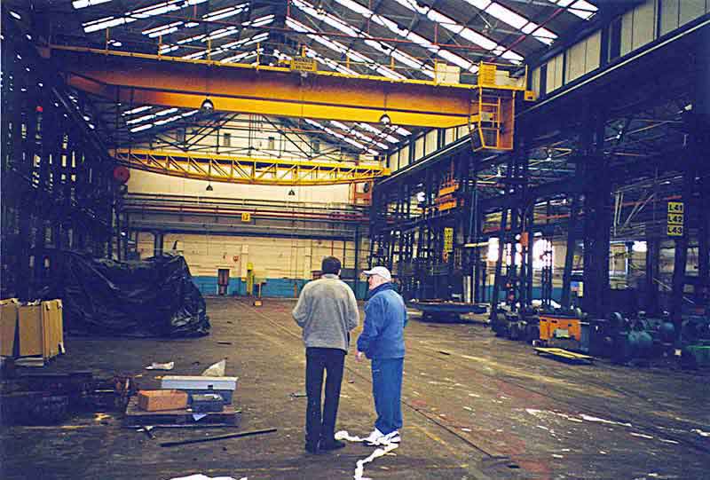
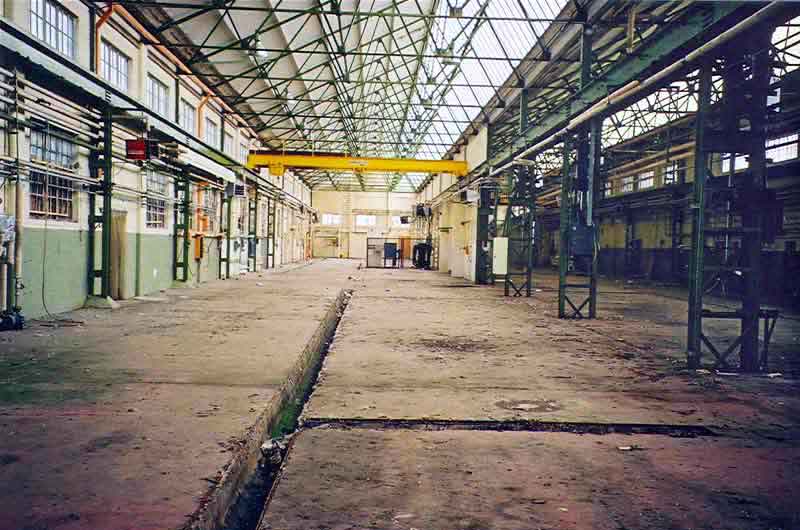
| Layout of Cranes in key workshops | List of the cranes existing at Westwood Works | Two Cranes in the Main Fitting Shop | Crane in Experimental Department | Hoist in the Machine Shop | Selection of Cranes and Hoists in the Fitting Shop |
 |
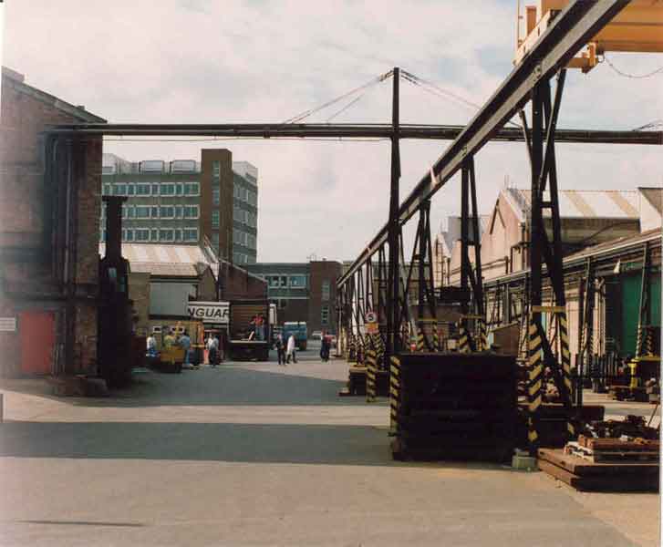 |
We believe that the Yard Crane was erected in 1953 or 1954. The area beneath this crane was used as a castings store. Ken "Eggy" Allen was usually in charge. | |||
Crane drivers were, by the nature of their work, interesting characters. Perched aloft in their tiny cabins, relatively isolated for most of the day (or night), they played a key role in ensuring a smooth flow of production. Much skill was needed, as well as an understanding of what was happening on the factory floor below. One wartime crane operator was said to have been able to stick a piece of chewing gum onto the bottom of his massive crane hook and lower it onto a marking out table to pick up a silver threepenny bit!
Two sets of two lifts existed in the 1932 multi-story office building, one set in the 1975 building and a single lift in the Holding Company building.
 |
 |
 |
 |
 |
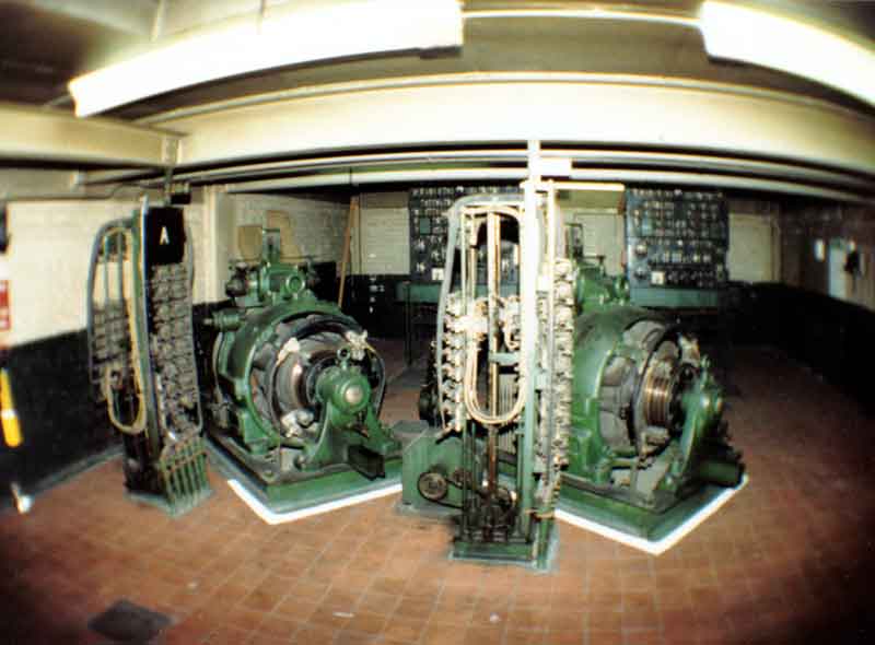 |
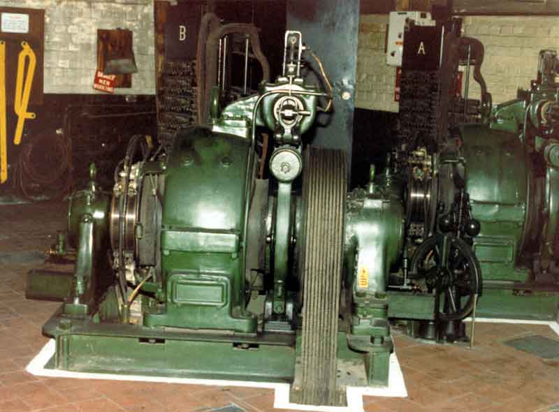
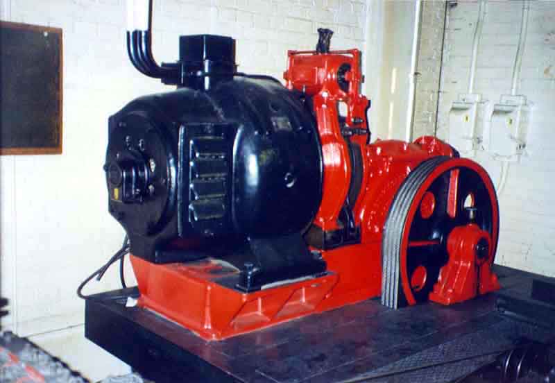
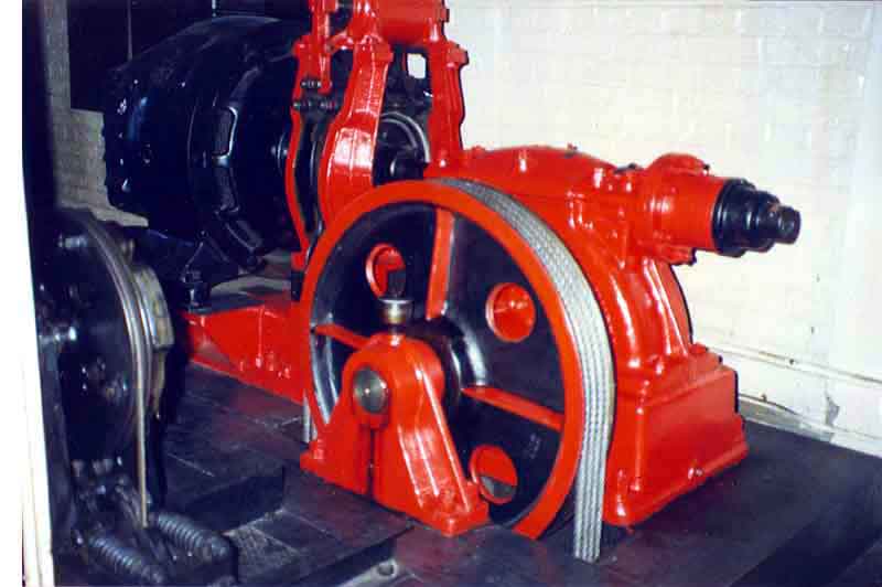
|
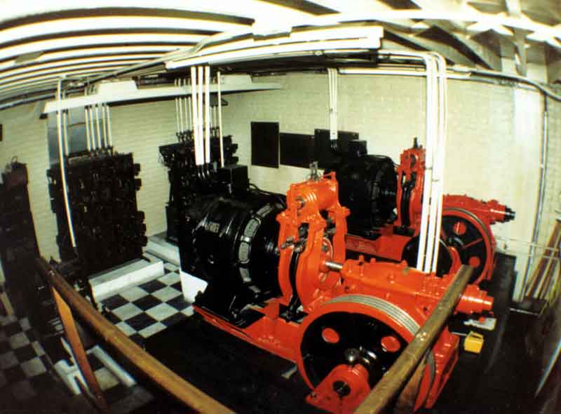
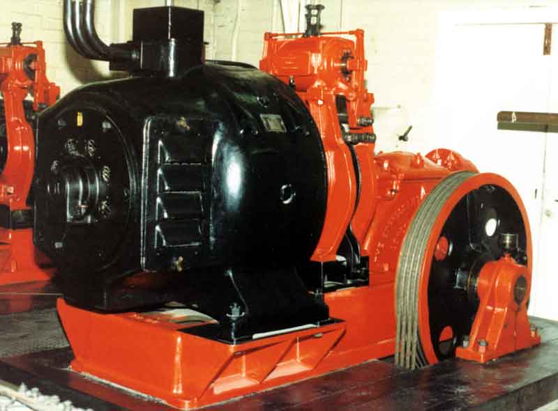
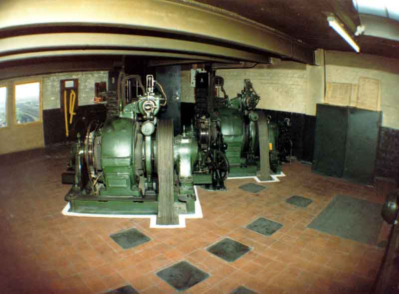
| The Express Lift House | Express Lift winding equipment | The Otis Lift House | Otis Lift winding gear | Otis Lift winding motors | ||
 |
 |
 |
| Switchgear for Express Lifts | ||
 |
||
| Winding equipment for the Holding Company lift |
In his survey of the company's operations - "Baker Perkins Dissected" , written in 1928, Barton Baker described the work of the maintenance Department as:
"All services which concern the preservation of the factory and offices in first class running order and/or physical condition may be classed under the heading of maintenance. These include, Millwrights and Repairers, Power House and Electrical Maintenance, Cleaning Staff, Yard Service and Shunting, Refuse, etc. and although this is a fairly formidable list the business methods of the Maintenance functions can be dismissed quite briefly.
All maintenance services with the exception of electrical services come under the Millwrights foremen who is, therefore, directly responsible to the Works Manager for the good order of the Offices and Works. Work such as cleaning, inspecting shafting, cranes, hoists, annealing chain slings and other gear otherwise liable to deterioration, keeping in good order drainage, roofs, gutters, paint, roads, etc. is done at regular stated intervals whereas repairing work and installing fresh plant is naturally a variable."
From the original machine tool maintenance work (Millwrights), electrical work, building and office services etc, eventually emerged the Plant Engineering Department with Alan Brockbank as Plant Engineer. He was supported by the Maintenance, Electrical, Building Services and Safety Foremen.
The Maintenance Department was situated towards the north-east corner of the site between the Fitting Shops and the Foundry.
 |
 |
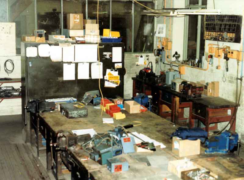 |
| 1987: Inside the Maintenance Department | 1988: Battery charging equipment (used until 1991) | Late 1980's: Maintenance Electricians shop |
The Maintenance Department housed a DC rectifier - the only source of DC power for cranes and lifts.
Westwood Works was heated by a system basically similar to that developed by Jacob Perkins' son, Angier March Perkins, in the early 1840s. (See - "Factory Heating" above). Mike Appleyard had joined Baker Perkins in 1960 as a Student Apprentice, with the H&V Department, training as a Heating and Ventilating Engineer. Some of his training was spent with the Maintenance Department and here Mike shares with us his experience of helping to repair part of Westwood's heating installation:
"The four inch pipe (100 mm) ran around the wall at a height of twenty feet (six metres), a metre below the level of the crane rail. Tom and I stood on the floor looking up at the pipe, which had to be moved, to make way for a large piece of equipment. "Go and fetch the forty eight inch stillsons, from stores" said Tom, I'll go and bring the ladders! The stores were accessed via a hatch in the wall, after ringing the bell a head appeared, "Can I have a pair of forty eight inch stillsons" I asked, and thirty seconds later they appeared, thudding onto the counter. It was all I could do to lift them, let alone attempt to use them. I carried them onto the shop floor, where Tom was busily putting up an extension ladder. "Right, you foot the ladder", said Tom "and I'll go up and undo that socket". He scrambled up the ladder with the stillsons over his shoulder, put them on the pipe, and pulled downwards with all his weight. Nothing moved, he tried again, finally taking both feet off the ladder and swinging on the handle of the stillsons, once again nothing moved.
By this time he was sweating profusely, and toyed with the idea of my joining him on the ladder, to add my weight and 'muscle', to his efforts. I suggested that (a) I was not particularly muscular, and (b) It would not really be safe, as there would be no one to foot the ladder. He reluctantly abandoned that idea, came down the ladder, and sent me off to the stores for a sixty inch chain wrench! If I thought the stillsons were heavy, the chain wrench was enormous and even heavier. I staggered back with them, and watched as Tom clambered back up the ladder. Even for him holding the wrench, putting the chain over the pipe, and locking it into position was a bit of a struggle. However he succeeded, and proceeded to go through the sequence as before, without managing to move the pipe.
I could see him looking around for inspiration and almost read his mind as his eyes spotted the crane. He was down the ladder in a flash, almost running down the shop floor to the crane controls, which dangled from the crane down to working height at floor level. I ventured to suggest that the crane would be lifting up, not pulling down, "Yes" said Tom, "but if we move the chain wrench to the other side of the socket, we will be able to use the crane to pull upwards, and that should do the trick".
Tom moved the wrench and manoeuvred the crane along its track into a position where he could hook it onto the wrench and use its power to move the pipe. Once in position he came down the ladder and inched the crane until it was taking some tension on the wrench. It really did seem to be working, however I pointed out the pipe was moving, in a vertical manner as the crane lifted it bodily off the pipe brackets. This was not the sort of detail to deter Tom, who proceeded to inch the crane hook up even further. He did not stop until the pipe itself began to bend, with the socket still firmly fixed!
After taking the crane hook off the pipe wrench, he found that not only had he bent the pipe but the wrench also, and the chain was almost welded to the pipe. It took a couple of hours with a large hammer, and a lot of brute force, to disengage the wrench from the pipe, at which Tom handed the tool to me and said "Take this back to the stores, and tell them it was bloody useless". At the best of times the storeman thought that all workmen were on the make, and to attempt to pass a hefty tool off as being 'useless', would go down like a pound of lead! I rang the bell and a head appeared at the hatch, after putting the mangled wrench onto the counter, I suggested that in Tom's words, they were "Bloody useless", and walked away. As I walked away I am sure he could see the yellow streak running right down the middle of my back, the storeman however said nothing, I was sure that the next time he set eyes on me he would.
When I arrived back Tom was explaining to a welder, where he wanted the pipe cutting, and as he had disturbed a large section, we had much more to replace then originally envisaged!
The pattern store was as its name implies a storage area for 'patterns' for the casting shop, Tom and I viewed our next job, he said, "Why they want to heat this place I'll never know", the store was large, racked out, and home to thousands of wooden patterns. No one actually worked in there, visiting the Store only to deposit or retrieve a pattern. He stumped off to bring back some ladders leaving me to view the problem, which seemed to be that the store was heated, as was most of the factory areas by banks of steam fed, pipework, running around the walls. The pipe was about one inch (25 mm) in diameter, a relic from a previous heating system, simply connected to a new steam source, with a the addition of 'steam trap sets', to remove the condensation, and return water to the boiler. Tom returned with two sets of ladders, put one in place scampered up the ladder, and proceeded to hammer 'seven bells' out of the pipework. The theory was that the scale in the pipe was effectively blocking the tube and not allowing the steam to pass through and heat the pipe; as a result the whole system was 'waterlogged, and cold. "Right, you start at the other end of the building and hammer the pipework to move the blockage, and we’ll put the system back into operation".
After a while Tom decided to remove the strainers from the steam trap sets, and run the condensate and detritus onto the floor. What a mess, the more we hammered the more the rubbish, poured out, and gradually the pipes began to warm up, eventually resulting in steam and hot water beginning to trickle out of the traps. Suddenly there was an almighty bang, a huge plug of rusty scale and water shot out of the first trap set and a blast of very hot steam billowed into the air, causing Tom, who was closest to scamper down the ladder and run, with the ladder, to the main shut of valves, situated at high level just inside the main door. At the same time as the stream began to push through the pipes, it came into contact with the cooler water, causing 'steam hammer'. With every 'thump' inside the pipes, the whole lot moved, danced would be a better word, on the pipe brackets. As Tom reached the shut off valve, the second trap set began to billow out steam, and as the blockage seemed to have cleared, the steam was hissing out at an ever increasing rate. Tom yelled, "The valve is jammed, hand me up a pair of stillsons", I shot down the store through the ever increasing cloud of steam, and handed him his small stillsons. "By now panic was setting in, Tom screamed, "Not them you daft b*****, the big ones", I once again obeyed with alacrity, and by now, and not a little alarm.
As the blockage gradually cleared, all the traps were letting off steam at an ever increasing rate. Through the haze Tom was battling with the valve, which had probably not been used in years, and stubbornly refused to budge. It finally gave out as the handle sheared off., Tom slid down the ladder, and shot out off the store, with me hot on his heels. He ran across to the boiler room, where a very perplexed boilerman, was watching with increasing anxiety, the gauges on his boilers, as the steam was being used faster then the plant could produce it. Tom yelled, "Turn off the circuit to the Pattern Store, there is a leak". As the valves in the boiler room were well maintained, the offending circuit was soon isolated. "What happened" said the boilerman, as the boilers began to recover and return to normal operation. Tom said, "That bloody steam isolation valve in the Pattern Store, is not working, they never maintain anything in this place, until it is knackered". Not a word about the filters he had removed on the steam traps, he looked at me and winked, "We'll go and see the damage".
The steam was by now turning to condensation, which covered every surface, "Open the big doors, we'll soon have this place dried out", said Tom. "Lets go and have some dinner, well put the filters back when the system has cooled down a bit”.
When we got to the canteen, the place was beginning to fill up, and some off the staff were moaning about the temperature in the room. Tom did not bother to inform them that the Canteen was on the same circuit as the Pattern Store, "By the time they find" out he said, "I'll have the heat back on, besides they will get back to work more quickly, if it is too cold in here!"
It did not take long to replace the filters , I was sent across to the Boiler House to ask the Boilerman to turn the steam back on, "Slowly", said Tom. I passed on the message, to which the boilerman retorted "He'll be wanting my job next, tell him I know what I'm doing". Normal service was resumed, and by mid afternoon the heat was back on to all areas. Not before Tom had been summoned by his boss to explain why the Staff Canteen had been cold at lunchtime. After the meeting he came out quite chirpy, the faulty valve having taken the blame and earned him some overtime, to replace it, when the steam could be turned off, without affecting other circuits".
Mike adds:
"My fondest memories are of my days, either in and around the workshops, and being out on site, which taught me that, life at the 'sharp end' was often difficult, cold, dirty, and a little cross on a drawing, represented a 6 inch cast iron valve, which could weigh a hundredweight or more!"
|
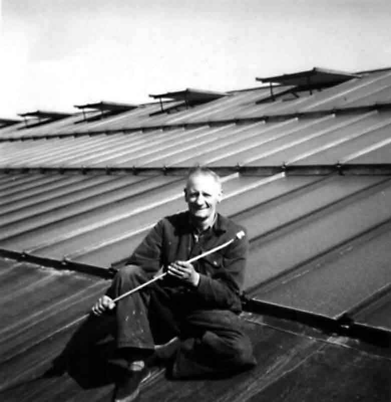
An important task in early Summer was to spray shading material onto the roof glass to help control the temperature on the factory floor. It all had to be washed off at the end of the Summer. Here is Jock (Hugh) Gavin at that task circa 1966. |
The factory roofing was completely replaced between 1974 and 1986.
 |
 |
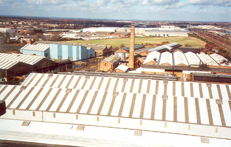 |
| Site Plan showing Roof replacement dates | Original Roofing | New Roofing |
Another little known Westwood asset was the "Glass Shed" - not made of glass but a store and workplace, housed in the Maintenance Department, where large sheets of glass, of different sizes and thickness, were kept and used to replace any damaged panes in the offices and factory areas.
All of the manufacturing areas in the factory had large expanses of glass in their roofs and some quite large panes of glass had to be replaced from time to time. Office areas also had some glass in their construction but this was mainly confined to relatively small areas in windows, doors or office partitions - most of these being a simple matter to replace. It was a somewhat different matter when the factory roof was affected.
Whenever a report was received of damaged or broken glass in the factory roof, Maintenance personnel would first seal off the area immediately below to keep out unauthorized personnel and to protect the employees. The next important task was to protect the machine tools below as any damage caused by glass or rainwater could have a very serious effect on production. Urgent replacement of the damaged glass was therefore essential and was given a high priority.
Joe Smith of the Maintenance Department, who worked on this important task, recalls the work involved - "Having removed the damaged glass, a new piece was measured and cut to size before being hoisted up to the roof by means of a 'block and tackle' arrangement - not always an easy task, particularly in inclement weather. 'Crawler ladders' were placed on each side of the opening and two Maintenance men placed the new pane of plate glass into position and ensured that the lead seals were made secure. In addition, as an extra precaution, 'grease strings' were also laid along these seals to prevent water from seeping underneath". The very large area of factory roof at Westwood (See "Roof Maintenance" above), meant that a constant watch had to be kept on the fabric of the roof to ensure that production on the shop floor below was not disrupted for too long a period.
 |
In 1988, not long before closure, the main road and pathways around the site were re-surfaced. This covered up the last remaining vestiges of the railway siding system.. |
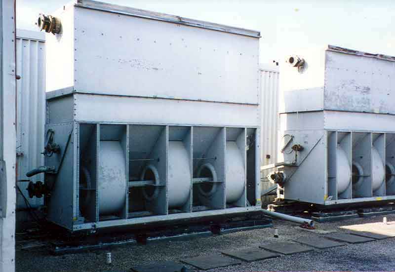
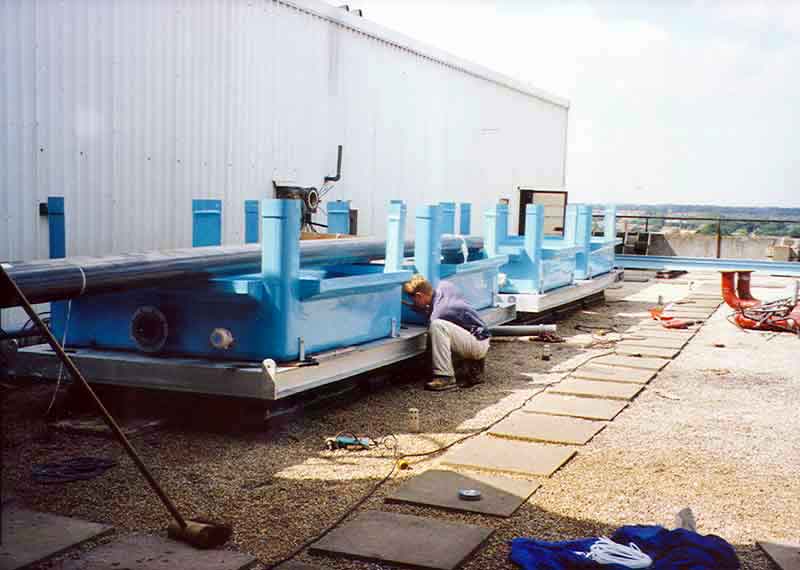
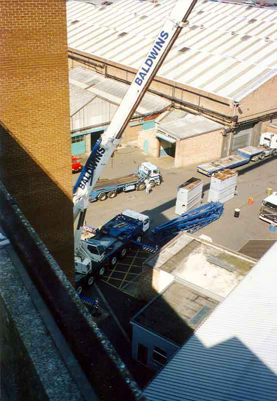
The air-conditioning cooling towers on the 1975 office block had rusted through by (date?) and were replaced. This required the services of a crane with a very long jib which lifted the new units from the main Works entrance onto the roof of the block.
 |
 |
 |
 |
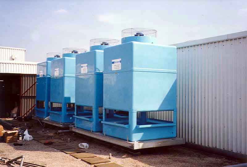 |
| The original Cooling Towers | The new bases in place | The crane | In mid-lift | The new Cooling Towers |
All content © the Website Authors unless stated otherwise.