|
Help | | | News | | | Credits | | | Search | | | Guestbook | | | Forum | | | Shop | | | Contact Us | | | Welcome |
Westwood Works 1903-2003 |
|||||||||||||||||
 |
 |
 |
 |
 |
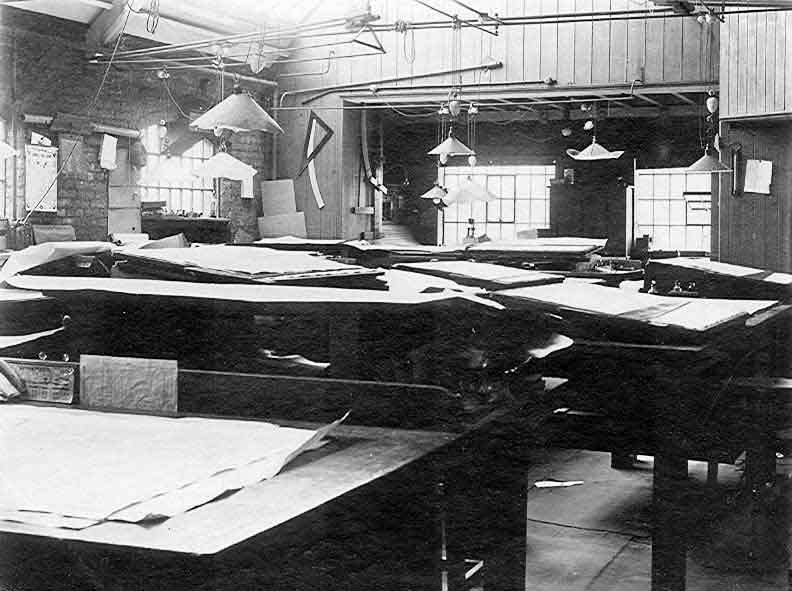
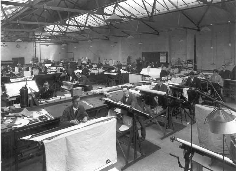
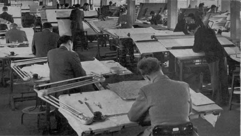
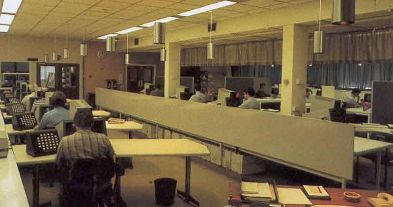
| The D/O at Willesden - early 1900's | Westwood D/O in 1923 | The D/O in 1961 | The CAD/CAM D/O - 1986 | 3rd Floor D/O in 1991 |
A glance at the first three photographs above might suggest that nothing much changed in the Drawing Office for most of a hundred years, indeed, it has been suggested that the only innovations had been the introduction of the propelling pencil and the replacement of the slide rule by the calculator. Certainly, the layout of the 1961 Drawing Office appears little different from that depicted in the earlier photographs and most of the day-to-day routines would have been recognisable by a draughtsman in the WP&P offices in Regent Square. However, the operation of the Drawing Office underwent a series of major revolutions in the 1960's and 70's. These affected not only the layout of the department but also the whole way in which the design function was managed and how designers and draughtsmen carried out their day-to-day responsibilities.
Some insight into the day-to-day activities in the Drawing office can be found in the reminiscences of Gordon Steels and Roland Maycock that are included in History of Baker Perkins in the Biscuit Business. An example of how a design team developed a new product can be found in History of Baker Perkins in the Foundry Business - Fascold. More pictures of life in the Drawing Office are shown in Inside the Offices.
The Drawing Office underwent something of a major cultural change in 1956 with the retirement from active management of Claude Dumbleton - followed a year later by G.D. Wilson. This ended a direct link with the "Willesden" era and, as a result, many changes took place in not only the characters involved but also the style of Drawing Office management at Peterborough. More details may be found in The History of Baker Perkins Ltd - The End of an Era and in History of Baker Perkins in the Biscuit Business - End of an Era.
This was a small but important section of the Drawing Office described by Barton Baker in his 1928 summary of the structure of Baker Perkins - "Baker Perkins Dissected" as:
"Schemes or Layout Section for preparing attractive "Sales" drawings to illustrate to prospective customers proposed arrangements of Plant they have in view, designed to solve the customer's problem in the most practical and remunerative manner."
The Plant Layout Section worked with the relevant design offices to ensure that the proposal being prepared not only fitted into the customer's existing building but also that access gangways were adequate for both operating the equipment and for routine and major repair purposes. The Plant Layout drawing was a key input into the "Erection Drawing" and took account of the existing steam, electrical, compressed air, etc., services in the customer's building and the practicability of extending these to serve the new plant. Another major consideration was the need for adequate foundations for the new plant, especially in multi-story factories. An effective liaison with the Estimating Department was essential, particularly if space limitations in the existing factory dictated significant modifications to a 'standard' specification.
A copy of the Plant Layout Drawing was carefully coloured and sent to the customer with the Final Quotation. Some of these could be described as "works of art" and undoubtedly contributed to the chances of obtaining an order. Dick Preston, whose first exposure to the Drawing Office was a period in the Plant Layout Section, recalls that it was an ideal place to learn about the Group's products in detail as a request for a Plant Layout Drawing could come from any of the company's sales offices. He recalls that the draughtsmen would often attempt to complete the drawing by Friday lunchtime so that a pleasant Friday afternoon could be spent applying watercolours.
 Bob Bains, who was deputy section leader under Peter Pocklington at the time,
produced this cartoon of the Plant Layout Section in 1959, housed on the 2nd
floor of the 1933 office block, as one of his regular Christmas cards. Those
who worked there will readily recognise the characters - Stephen Hargreaves,
the director in charge of the Drawing Office is deep in conversation with Peter
Pocklington and John Mowl in the foreground while Bob Bains is almost submerged
under piles of paper. Who are the young couple at the third board from the
bottom in the middle row?
Bob Bains, who was deputy section leader under Peter Pocklington at the time,
produced this cartoon of the Plant Layout Section in 1959, housed on the 2nd
floor of the 1933 office block, as one of his regular Christmas cards. Those
who worked there will readily recognise the characters - Stephen Hargreaves,
the director in charge of the Drawing Office is deep in conversation with Peter
Pocklington and John Mowl in the foreground while Bob Bains is almost submerged
under piles of paper. Who are the young couple at the third board from the
bottom in the middle row?
While discussing the role of the Drawing Office, we will also look at the role that Industrial Design played in revolutionising the way in which product design was carried out at Westwood and at the introduction in 1977 of Computer Aided Draughting (CAD), and its development to link with Computer Aided Manufacture (CAM). Both were to have a profound effect on the way in which different departments of the company inter-reacted, broke down barriers between these departments and significantly improved the company's competitiveness.
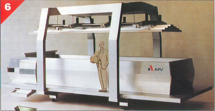
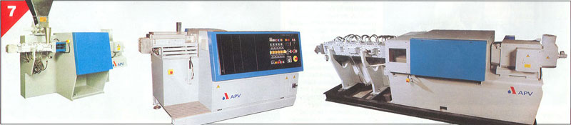
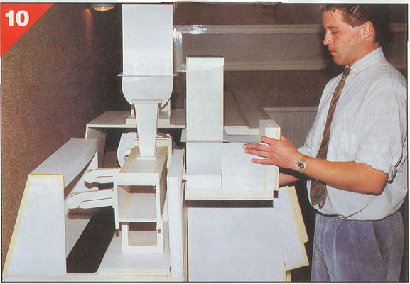
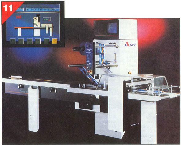
This description of how the Industrial Design process worked at Baker Perkins is by Roger Coulthard - Industrial Design Manager.
"Industrial Designers can get a little upset if people think that their one concern is to make things look stylish - and the trend for "Designer" labels on fashion products has not helped at all! It's wrong because real design is not about hype, or overpriced jeans. It's a systematic process aimed at giving customers competitive products that meet their real needs and it relies upon well-managed co-operation between a variety of specialists".
"Attention to such detail helps provide customers with attractive, clean, safe and easy-to-use plants and gives the Company a competitive advantage in the market place".
It is fair to say that Baker Perkins was among the first in the UK to harness these emerging technologies and their effect on working practices at Westwood was significant and long lasting. It is felt appropriate that these major changes in the way people worked and the story of how these radical changes were assimilated by the Westwood management and employees should have their place on this Website.
Before examining the changes brought about by the introduction of the Industrial Designers it is worth stressing one aspect of drawing office management prior to Divisionalisation that put the designers at a considerable disadvantage. Gordon Steels remembers:
"Before divisionalisation, and during its early years, no Drawing Office personnel, including designers, senior engineers etc, were allowed to know the cost of the designs for which they were responsible.
It seems unbelievable now but this was a fact at the time. Costs were strictly guarded by the chief estimator Gerald Simpson - from his department on the 4th floor next to the commercial offices. (Later chief estimators were rather more flexible in their approach).
So the situation was that those directly involved in the design of the new machines and who actually determined the cost by what they designed, were not allowed to know the actual costs, with the result that by the time the estimating department had done its job using the finished, detailed drawings, already a lot of time and money had been spent on what could have turned out to be an over expensive design - which often happened. It was a crazy situation and hard to believe". (See also History of Baker Perkins in the Biscuit Business).
(See also Departments at Westwood Works)
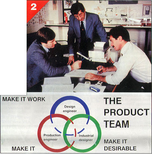
The objective of any design exercise is to end up with a final product that has more than a passing resemblance to what the salesman thought he had sold and the customer expected to receive. However, the historic design process had many faults. The designer interpreted an idea for a new product as described by the salesman and produced the drawings. These were sent to the production engineers, who interpreted how it should be manufactured in a way that suited themselves, the manufacturing department being left to make the machine as best it could. If the final machine turned out to be how the designer first envisaged it, let alone what any customer would want to buy, was something of a matter of luck. Much time and money was wasted at the boundaries between disciplines. A way was needed to cut through this time-consuming and wasteful procedure. Design management needed to become an iterative, not a linear, process.
The introduction of Industrial Designers into the business in the mid 1960's can perhaps be described as a "quiet revolution". What possible benefit could a few young ex-art students bring to a highly technical engineering organisation? The established view of Industrial Designers was that they were "stylists" brought in after a design had been finalised to make the product look "pretty" by playing around with the machine's guards.
It soon became clear that the "ex-art students" were first and foremost excellent communicators who could create a bridge between the marketing, design, production engineering and manufacturing functions. The different functions now became a "product planning team" with the Industrial Designer as a catalyst or translator whose most useful role was to keep asking, "Why are we doing this?" and "What benefit does that design feature bring?"
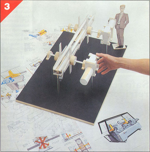
One very important outcome from this team approach was that the idea that the designer should not know the cost of his product was swept away. Ideas were converted into sketches by the Industrial Designer and immediately costed so that no time was wasted in producing finished drawings for parts that would prove too expensive to manufacture. The designer knew what his machine would cost before it left the Drawing Office.
With all members of the "team" now being absolutely clear as to what the customer needed and how the new product would be used, the development to delivery cycle - the time taken from the birth of a concept to its delivery to a customer - shrank, typically by as much as half. Individual departments worked in greater harmony to a common goal. A "quiet revolution" had taken place and how people worked, from the salesman to the fitter, would never be the same again.
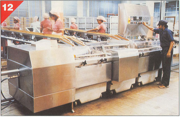
It was not only the Drawing Office that had to accept a change to what had gone before. The company's sales teams and customers were faced with a new conception of "quality" and "value for money". The new designs looked significantly different from those that everyone was used to. In the process of designing in only what was necessary to do the job, much of the historic "good, robust construction" that had been the hallmark of Baker Perkins equipment had given way to a modern, lighter, easier to operate, more hygienic look. This was not to everybody's taste at first and startled some customers . Having in the past equated "quality" with solidity of construction they were soon persuaded that the new machines were competitive on price and specification and, more importantly, performed at least as well, if not better, than earlier equipment. A change in the market helped here. Customers were themselves experiencing a revolution - under great competitive pressure, more alert to change and coping with shorter product life cycles as their end-market developed in response to increases in customer per capita income. Machinery was no longer expected to last a life time - it was more important that it more closely matched the way in which the customer operated his business.
(see also Departments at Westwood Works).
Fundamental as this change was, it was insufficient to transform the company's fortunes on its own. Competition in the market place remained keen and an improved speed of response was vital. Another revolution was needed in the Drawing Office. Investigation showed that a designer spent only 10% of working day drawing whereas a draughtsman spent all day at his board, much of this work being repetitive and routine. Overall, only one third or less of the available time was spent actually drawing. The main impetus for change was, therefore, the need to improve the productivity of the D/O and substantially reduce the cycle time through the engineering departments. A key potential benefit was perceived to be the freeing up of precious technical manpower for more creative engineering duties.
After some lengthy investigations, and despite it having been until then confined to specialist applications, the appropriateness of Computer Aided Draughting to a general engineering operation like Westwood was agreed. The first 4-terminal CAD/CAM system was introduced in the spring of 1977.
It was the first Unigraphics system to be installed outside of North America. The software ran on a Data General S200 with 128 kilobytes of main memory (you read that correctly, less then 0.13 MB), a 96 MB removable disk drive, a 9-track backup system, a paper tape punch/reader and a Calcomp 960 plotter. This turnkey configuration, including the Unigraphics software, cost over $400,000 (in 1977 dollars) and required the setting up of special facilities including an air conditioned room for the CPU and disk drive and special controlled lighting for the terminal room.
NOTE: In July 1977, what was basically a duplicate of the Peterborough system, was installed in the Saginaw MI factory. (See History of Saginaw)
An early decision was that, although Westwood had an expert and progressive computer department, the whole of the new system would be conducted by mechanical and production engineers with no previous experience of computer systems other than as users. The designers, draughtsman, tooling draughtsman and N/C (Numerical-Control Machine Tools) programmer should find it as natural to use CAD/CAM as it would be to use a calculator or any other item of office equipment. To work through a computer monitor screen should become as natural as using a drawing board. Another early decision was that the new equipment should be blended into the existing office environment and not be hidden away, operated by "specialists". CAD terminals would exist alongside traditional drawing boards
Financial justification was based on productivity. However, the less tangible benefits of cycle time reduction, greater accuracy, better quality of output and the creation of an engineering geometry data-base became increasingly important.
After some initial reluctance to volunteer for training, drawing office personnel responded well to the new methods of working. One week of basic training was followed by three weeks of on-the-job instruction. Terminal operating time was valuable and each user was allocated a four-hour session for which users were encouraged to prepare sufficient work in advance. Although not much different from normal D/O routine, the user had to exercise more forethought and plan his activities more thoroughly.
With the need to operate the expensive CAD equipment over a longer period of the day, working hours had to be adjusted for some people. A long morning shift was followed by an afternoon/evening shift and, for a time, a night shift. In late 1977, a second 4-terminal system was installed, another eight terminals in 1978 and, by August 1982, there were twenty-five terminals. By this time, the look of the D/O had been transformed as shown in the last two photographs above.
In mid-1978, the group newspaper - "Contact" - interviewed a number of the drawing office staff who had been trained on CAD. Their experiences in coping with the huge technology change are re-printed below and make very interesting reading.
"Brian Watson runs the printing machinery CAD unit. He was amongst the first group of Baker Perkins people to go out to California for training. “I had heard about CAD before I went to California, but I imagined the emphasis would be on mathematical calculations rather than graphics. I was pleasantly surprised. There were seven of us on the course and it was very well planned. The emphasis was on practical use rather than theory. We were thrown in very quickly.
“I suppose after a year, the shine is beginning to wear off a little. I look upon CAD as being a tool to do a job. The more familiar you get with it the more you see its limitations.
“We now have twelve people trained from the printing drawing office. The training time is four weeks. Most people seem to take to it pretty well in that time.
“Of course, you have to be selective about what jobs are most suited to the system and it is particularly good for repetitive jobs.”
Vic Spencer is a senior design engineer with the printing machinery division. Vic was trained to use CAD in Peterborough, but he has also had special training for something called GRIP. This is short for Graphics Interactive Programming.
Vic tells us that this is a computer language which the United Computing Corporation has developed, enabling drawings of certain units or components to be reproduced very rapidly without going through the whole process of drawing them line by line. Although something like a printing side frame will take Vic six weeks to programme, once on the system, a size change can be reproduced in half-a-day. This compares with about ten weeks on the drawing board.
Vic says of CAD “I think that when we have really learned to use it correctly it will have great advantages. Certain operations are still quicker on a drawing board, namely dimensioning, but CAD comes into its own where calculation or duplication are involved.
“The better you get to know the system the better you use it. Recently I have only used it for short spells working on the drawing board in between times, simply using it as a tool to eliminate certain otherwise laborious tasks. It is a big step forward in drawing office work.”
Mick Emblow is a design engineer with the printing machinery division. He has been using CAD since last August.
“My first reaction was that the whole system was too complex for our sort of work. From what I’d read about it, CAD seemed more suited to the mass production industries.
“After nine months on CAD, however, I am now convinced that it is a powerful tool, but I still think we are a long way from getting the best out of it.
“It is certainly not the answer to everything, but there are some things it is very good at. Although it becomes easier to use as time goes on, at first it is a bit like learning to draw with a typewriter.
“How people get on with CAD very much seems to depend on their personality. Because it is so fast to respond, it creates a higher degree of stress than working at the drawing board. Some people can take that, others can’t.
“At the end of the day, though, the only real test of whether CAD has worked will be whether we are getting the work out of the door faster. This is the only thing that will bring greater profitability and prosperity in which we can all share.”
Jim Pinchen is a design engineer with the biscuit division, working mainly on biscuit forming.
“I had used computers at university to do calculations but the graphics side of CAD surprised me. The potential of the equipment is immediately obvious.
“It seems that almost every time you use CAD you discover something new that it can do. We are still learning the techniques of using it and obviously over the years we will get better.
“The speed with which designers can now work is already putting great pressure on the decision-making process. Management will have to re-think this process in order to keep the work moving.
“CAD allows the designer more time to think about the job and I think the biggest potential is in design work rather than draughting.
“Working on CAD is completely different and very challenging, but it is quite amazing just how adaptable people are.
“The limitations at the moment stem from the fact that the terminal time has to be carefully rationed. The day will obviously come when there is a terminal for everyone to use when they want and that will be much better.
“It is strange that drawing offices have been almost the last section of industry to be really affected by technology of this sort. I think that design engineers have suffered in recent years by having to adapt to technology in other areas of engineering. CAD could give the initiative back to us.”
David Marrington runs the CAD unit for the food divisions (bakery, biscuit, chocolate and confectionery). He went to California for his training along with the initial group from Baker Perkins.
“I went to California with a completely open mind about CAD. The one week’s training, which perhaps should have been longer, was a tremendous experience and I was pleasantly surprised by the capabilities of CAD.
“I believe in looking to the future and we must learn to live with this sort of technology. Working with CAD is a challenge and people have to be given time to adjust. They need to be reassured and the company must be aware of the pressures on people using the equipment.
“We are developing the systems we use as we go along. You have to be strict about routine procedures because it is too easy to lose work if someone makes a mistake.
“We have no one else to turn to for advice on this. Brian Watson and I have different ways of working but we compare notes quite regularly to see what we can learn from each other.
“CAD is undoubtedly very powerful and a great help to designers. It will, however, put an increasing amount of pressure on the decision making process because of the extra speed of the work.” "
By the mid-1970's, a number of numerically-controlled machine tools had been introduced into the factory and the very obvious link to CAM (Computer-Aided Manufacture) began to be developed. The goal of significant cycle-time reduction and increased productivity could now be achieved. The flow of production-engineering information (and as important - mutual understanding) between design and manufacturing improved dramatically. The designer could now send manufacturing instructions directly to the machine tool.
All of these technological advances had to be discussed and their implementation agreed with the multiplicity of unions represented on the Westwood site. The historic strength of the relationship, built up over many years, between management and workers, ensured that this process proceeded remarkably smoothly (see Unions at Westwood Works).
Working practices at Westwood had taken another giant step into the future.
All content © the Website Authors unless stated otherwise.